HVAC, ventilation and hot water for an office building
Design for a 2,100 m² office building in Murcia — VRF system with heat recovery, R32 refrigerant.
I design mechanical hardware end to end in SolidWorks — from requirements to calculations, FEA, drawings and the test rig that checks them.
 Certified SOLIDWORKS Design Professional (CSWP) and Associate (CSWA), Dassault Systèmes (2026)Verify CSWP ↗ · Verify CSWA ↗
Swipe sideways to see the full matrix →
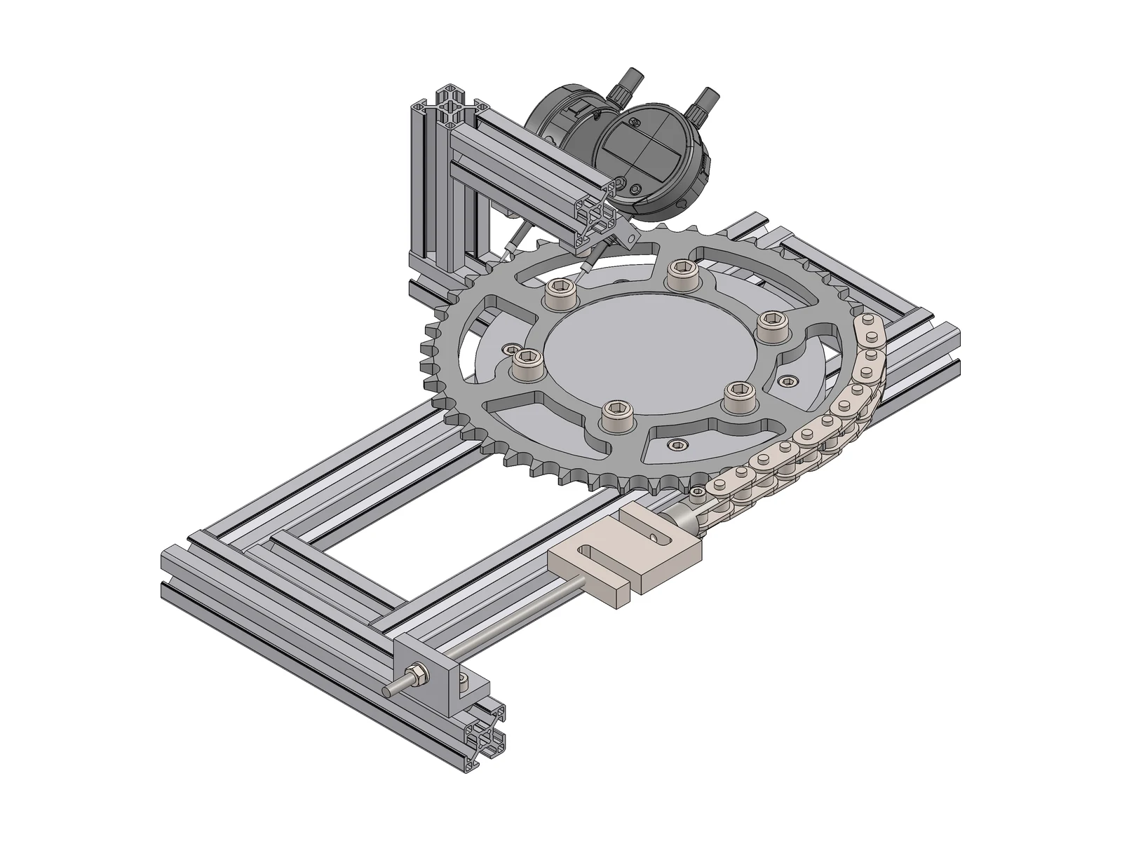
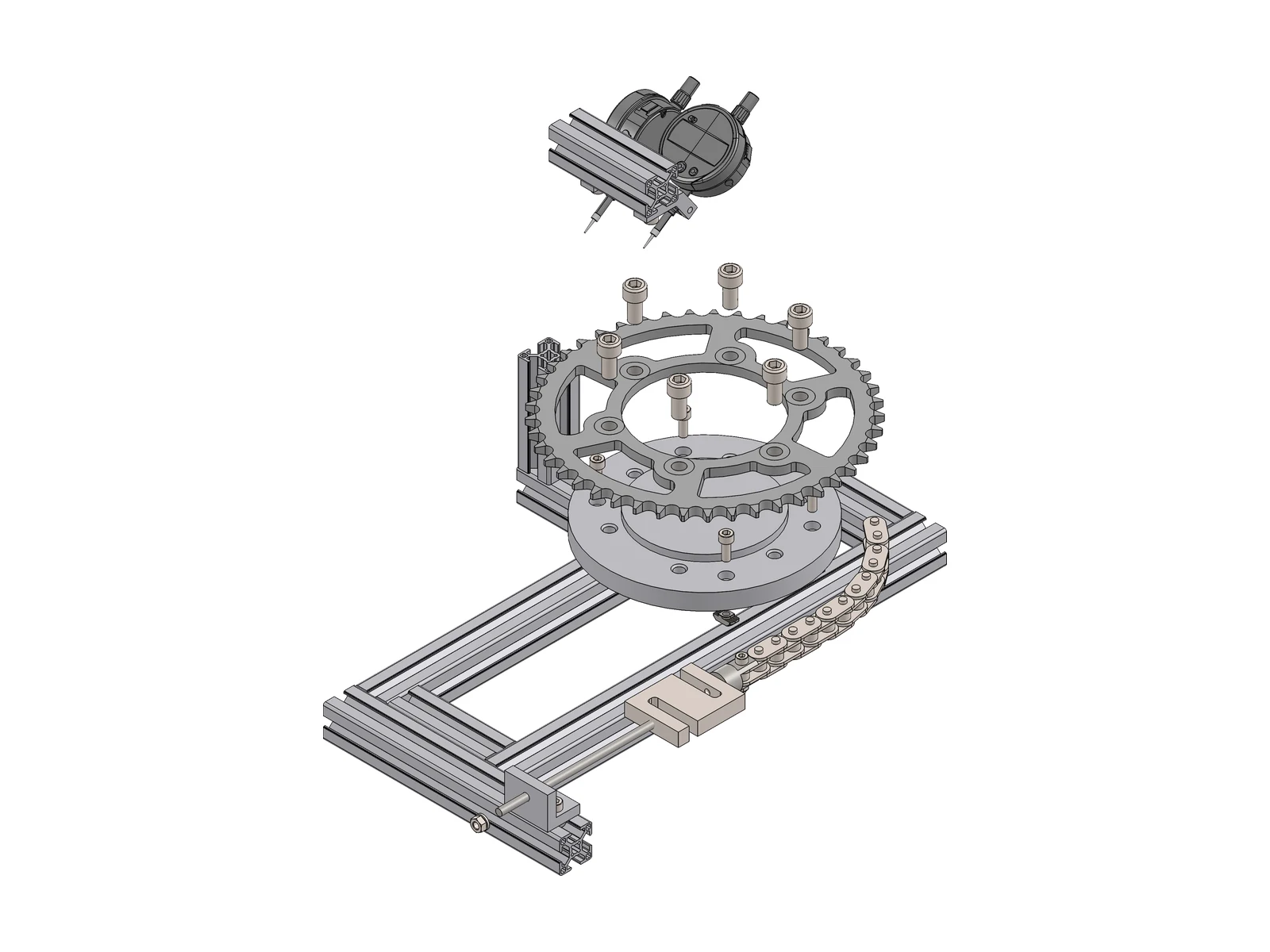
Validate the FEA model of the R6 sprocket (project 02) with a real measurement.
A threaded-rod tensioner loads the chain; a load cell (Phidgets, 100 kg) measures the force.
Differential rotation, read with two Mitutoyo digital indicators.
In steel the tooth moves only about 0.003 mm at test load — equal to the indicator accuracy. So the test uses a laser-cut PMMA replica, with a predicted reading of ≈ 0.054 mm. The replica tests the model, not the steel part.
Adjustable 30×30 aluminium-profile stand with two 6082 clamps designed for machining (Ø8 H7 bore, slot, M4 clamping screw). The CAD model showed the indicator tips would clash with the adjacent tooth, so the indicators are mounted at 35°.
A3 assembly drawing with exploded view and a 23-item BOM (Mitutoyo, Phidgets, Motedis). 58 components.
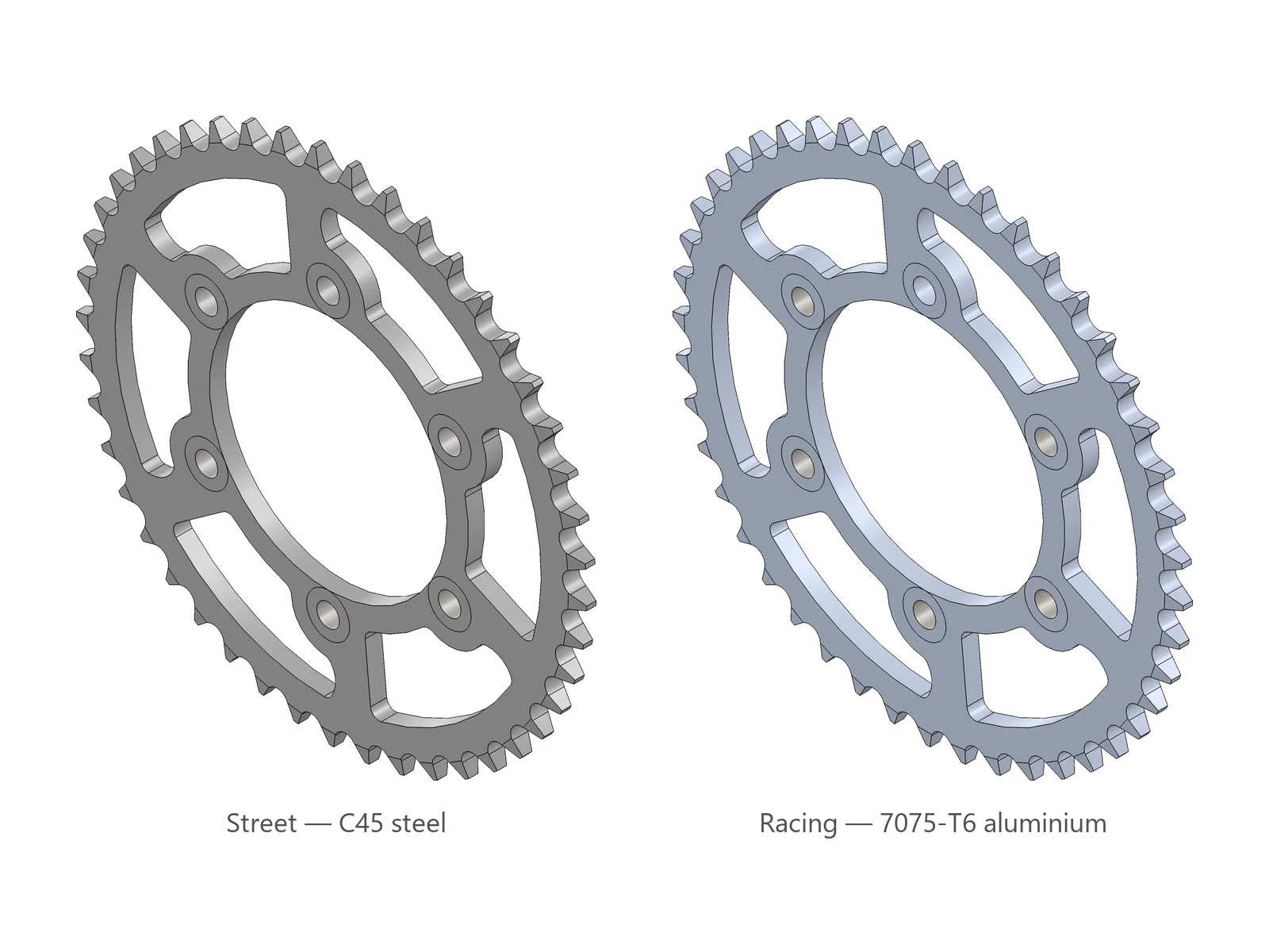
45 teeth. Street in C45 steel; racing in 7075-T6 aluminium, 64 % lighter.
Analysed at first-gear sprocket torque (1,035 N·m, from engine torque and gear ratios). The first design reached a safety factor of 1.12; redesigned windows and quenched-and-tempered C45 raised it to 2.1 (racing version: 2.4). Verified with a mesh convergence study and hand calculations.
Manufacturing drawings with the Ø110 H8 bore as datum.
Milling program (22 operations) and two-setup turning. CAM cycle-time estimate for the Ø110 bore: 0.86 min turning against 42 min milling.
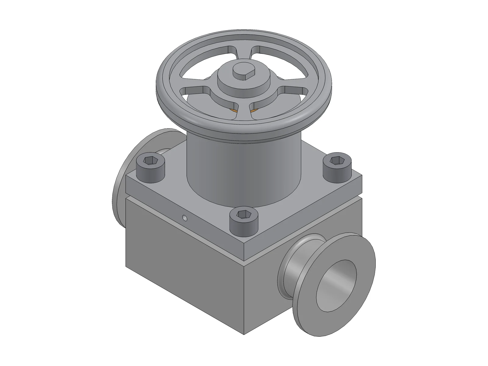
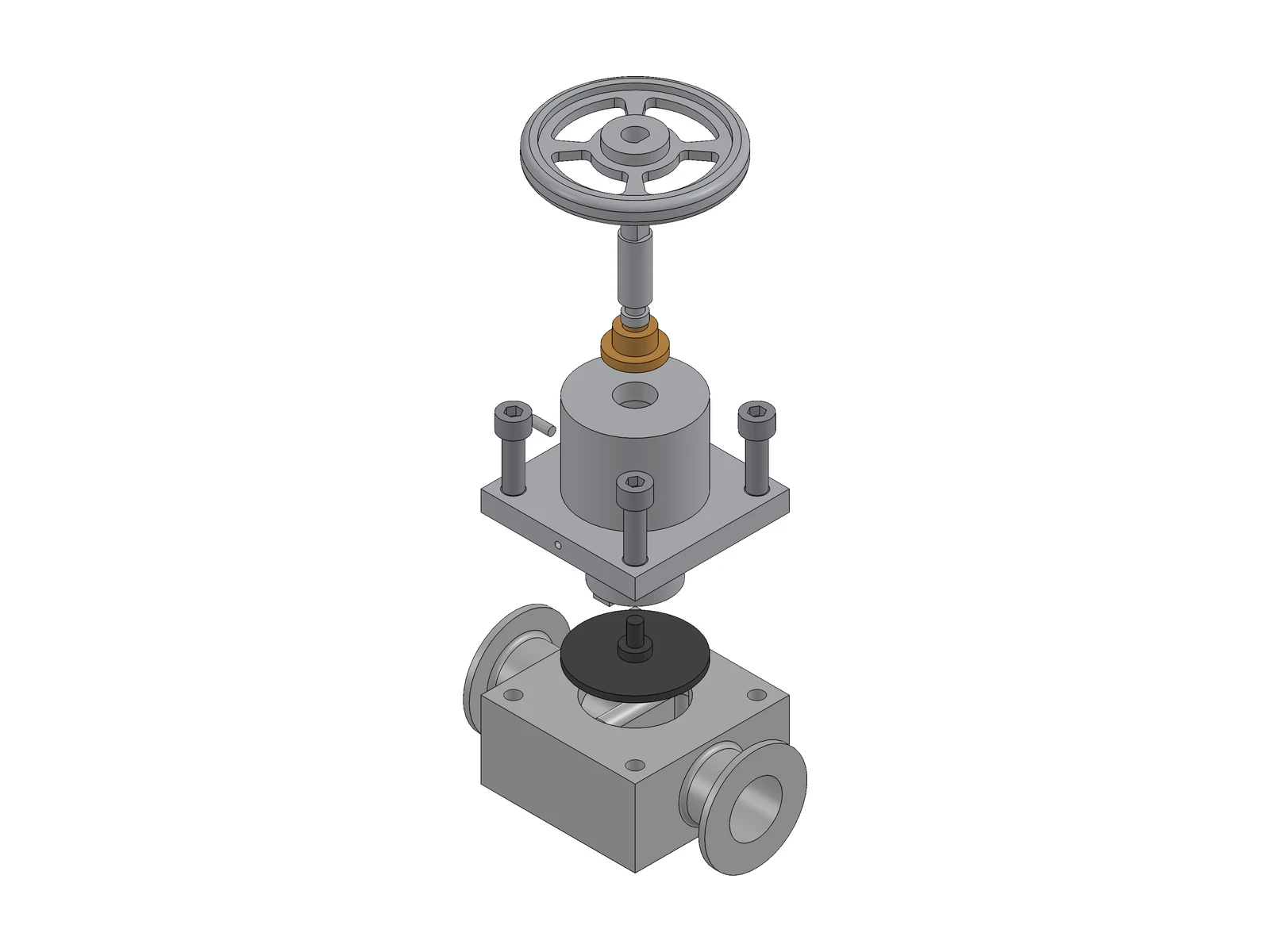
From a written requirements specification to a 12-component assembly (Tr12×3 lead screw, bronze nut, Ø80 handwheel).
Hand calculations for body wall thickness, closing force, bonnet bolts and lead screw. Body FEA at the 15 bar test pressure, with a mesh convergence study.
CFD Kv–stroke curve used to set the 12 mm stroke.
Assembly drawing with BOM, and a drawing of the 1.4435 stainless-steel body with ISO GPS tolerancing: datums, flatness, perpendicularity, and position with a projected tolerance zone.
Selected stroke: 12 mm, Kv 11.3 m³/h. CFD points at 4, 8, 12 and 16 mm — SolidWorks Flow Simulation, water at 20 °C. Hover or tap a point.
Not fully drainable.
The bonnet bolts need only 2.6 N·m. A standard M8 tightening torque gives about 7× that preload and would over-compress the diaphragm.
SolidWorks Simulation, root seated in a body socket and bolted, motor and propeller as a 70 g mass on the motor screws. Dashed line: 130 Hz.
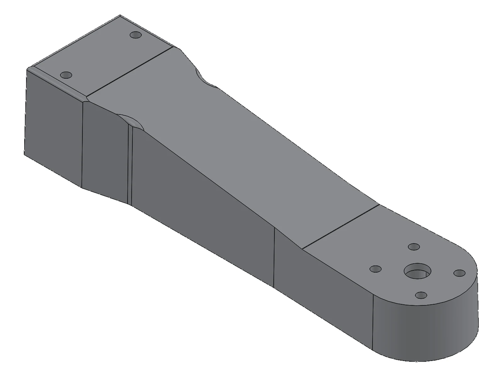
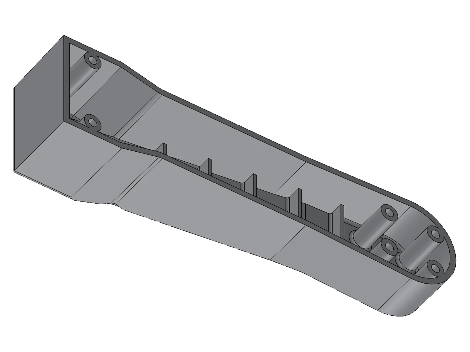
Assumed 1.5 kg quadcopter with a 2:1 thrust-to-weight ratio (7.4 N per motor), 28xx motor on a 16 × 19 mm M3 pattern, 120 mm free arm and a channel for the ESC wires. First vibration mode ≥ 130 Hz: 20 % above an assumed hover speed of 6,500 rpm (108 Hz).
PA6-GF30 (BASF Ultramid B3WG6, black), with conditioned properties (5.7 GPa, 100 MPa at break): the conservative values for an outdoor part.
Parting line on the underside, straight pull. Uniform 2.4 mm walls; 1° draft on walls, 0.5° on ribs and bosses; 1.4 mm ribs (about 60 % of the wall) that leave a passage for the wires; cored bosses for M3 screws inserted from below; R1 inside and R1.5 outside radii; gate planned at the root.
The first modal check failed (89 Hz). Tapering the depth from 32 mm at the root to 20 mm at the motor doubled the vertical stiffness, but the in-plane mode, now the first, sat at hover speed (108 Hz), where propeller imbalance excites it. Widening the section to 32 mm put both modes above the target.
Maximum von Mises stress 4.9 MPa in a 4 g hard landing, against 100 MPa at break: the arm is driven by stiffness, not by strength.
Design for a 2,100 m² office building in Murcia — VRF system with heat recovery, R32 refrigerant.
Belt load 1.3 kN at 2.4 m/s, about 3 kW. Design power with service factor, belt type and number of belts, pulley geometry (diameters, centre distance, wrap angles) and shaft sizing.
Low-voltage electrical installations to the Spanish Low Voltage Regulations (REBT): cable sizing, voltage-drop and short-circuit calculations, single-line diagrams, AutoCAD drawings and permit documentation.
Heat load calculations and equipment selection, supplier quotes, AutoCAD installation drawings, on-site support.
Advanced timed hands-on exam: parts from drawings with linked values and equations, configurations and design tables, assemblies with advanced mates, collision and interference detection. Verify certificate ↗

Timed hands-on exam: part modelling, assemblies with mates, drawing views and mass properties. Verify certificate ↗
Top 150 worldwide in Mechanical, Aeronautical & Manufacturing Engineering (QS World University Rankings by Subject 2026) and 2nd in Spain in Mechanical Engineering (ShanghaiRanking 2025).
SolidWorks, CSWP-certified (parts, assemblies, configurations, drawings) · GD&T (ISO GPS), ISO 2768 · BOMs · AutoCAD
Hand calculations · SolidWorks Simulation (FEA) · Flow Simulation (CFD) · heat load calculations · MATLAB · Excel
Design for CNC machining and assembly · SolidWorks CAM (milling, turning)
Pneumatic and electro-pneumatic circuits with a PLC (university labs)
Spanish and Catalan (native) · English (upper B2, Cambridge B2 First) · German (beginner)